What is PLC Ladder Logic?
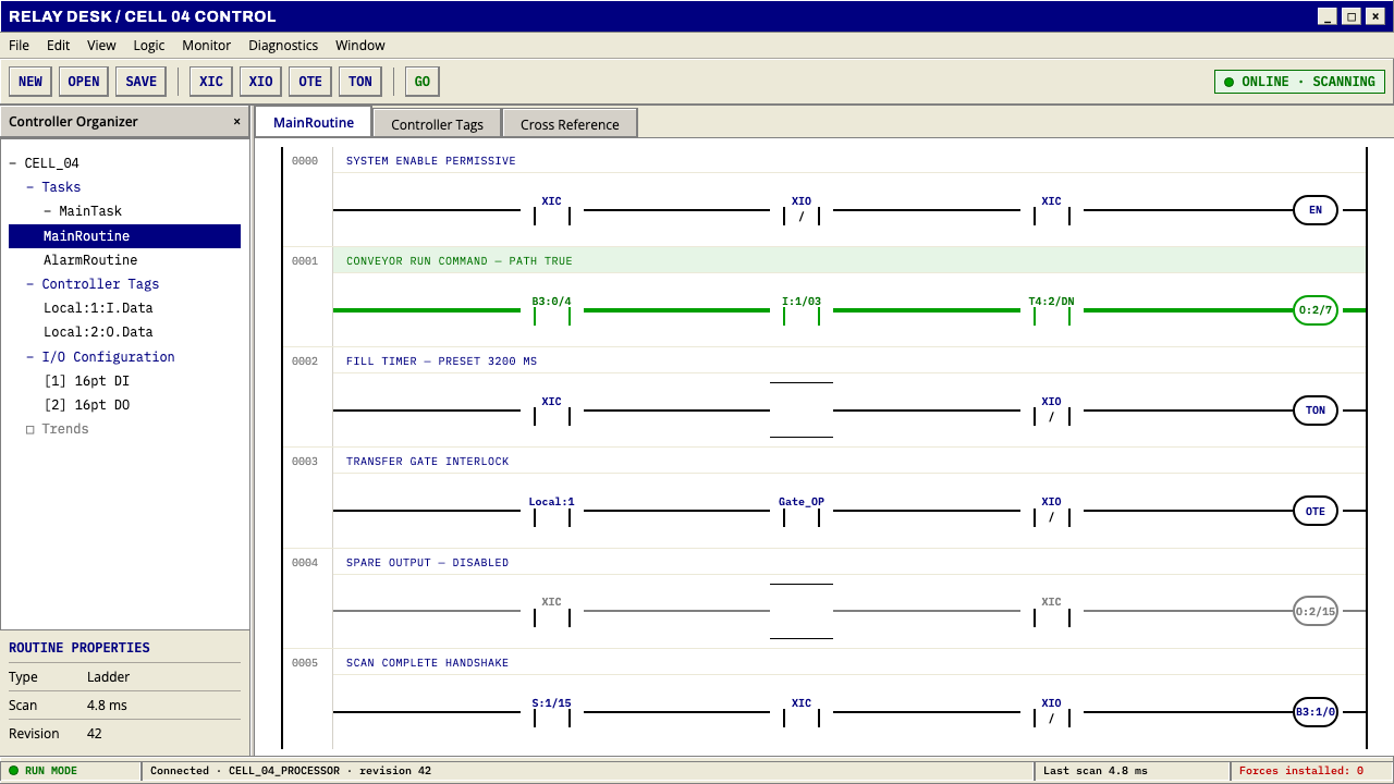
Ladder logic is a wiring diagram that happens to execute: black rails, navy mnemonics, and a single green that means one thing only — current is flowing.
PLC Ladder Logic in brief
PLC Ladder Logic is the visual language of the programming editors that ship with industrial controllers. A white canvas is crossed by two vertical rails, and between them run horizontal rungs, each one reading left to right as a chain of conditions that ends in an output coil. The look belongs to the years from 1990 to 2020, when these editors were native Windows programs — RSLogix on the Rockwell side, the LAD editor inside Siemens TIA Portal — wrapped in the grey, bevelled chrome of that generation of operating system.
It is an artefact rather than a movement. Nobody designed it to be admired; it was designed to be read by someone standing in front of a halted machine. Its conventions — contacts that stand for conditions, coils that stand for outputs, rails that stand for power — descend from the relay schematics that came before the programmable controller, and the editor preserves them so that an electrician can read software the way they read a wiring drawing.
The defining signal is state. When a rung evaluates true, the editor lights the conducting path green, instruction by instruction, from the left rail as far as current can travel. Everything else on screen — the white ground, the black rails, the navy instruction names, the grey tool strips — exists so that this one change is legible at a glance. A page built in this language is therefore quiet by default and speaks in a single colour only when something is true.

Where does PLC Ladder Logic come from?
Before programmable controllers, industrial machines were controlled by banks of electromechanical relays wired together inside cabinets. The wiring was documented in a schematic drawn as two vertical power lines with horizontal lines strung between them, so that the page looked like a ladder standing upright. Each rung showed what had to be closed before something downstream was energised: a limit switch, a push button, the contact of a motor starter, and finally the coil of the relay or motor the chain was meant to drive. Changing a machine's behaviour meant changing its wiring, with a screwdriver, one terminal at a time.
The lineage this system cites begins in 1968 with the Modicon 084, the controller associated with Dick Morley and his firm Bedford Associates. The 084 took its name from a project number, and the Modicon brand was short for modular digital controller. The customers who wanted such a machine were car makers, tired of tearing out and rebuilding relay cabinets at every model changeover. The decisive design choice was not technical but linguistic: the new machine would be programmed in a notation the plant's electricians already knew. Ladder logic is that decision made visible — software dressed as a wiring drawing, so that the people who kept the factory running would not need to learn a new language.
At Allen-Bradley, later part of Rockwell, Odo Josef Struger is widely credited with shaping the category the industry came to call the programmable logic controller, during the years when such machines were spreading through North American plants. In the 1990s the notation gained international standing when IEC 61131-3 defined a family of controller programming languages: Ladder Diagram sits beside Function Block Diagram, Structured Text, Sequential Function Chart and, in the early editions, Instruction List. The standard did not replace ladder. It recognised that ladder had already won the shop floor.
From the 1990s until roughly 2020, programming moved off dedicated terminals and onto Windows PCs, and the ladder acquired its familiar frame. The diagram sat on a pure white canvas inside grey toolbars, panels and dialog boxes whose raised and sunken edges came first from Windows 2000 and then from XP. When a technician connected to a live controller, the editor painted every conducting element green. That green became a diagnostic language: follow it from the left rail, and the first element that stops being green is where the fault lives. This design system refuses to modernise any of it, because the aim is to reproduce the artefact itself — the screen a maintenance technician actually troubleshoots from at three in the morning with the line down.
What defines the PLC Ladder Logic look?
Rails and rungs
Structure is the whole composition. Two heavy black rails run the full height of the canvas; every piece of logic hangs on a horizontal rung between them, read left to right and top to bottom. Nothing floats free of a rung. The geometry is strict right angles with thin, even outlines, and rungs are numbered down the left margin, so position on the page carries meaning in the way a line number does in code.
White canvas
The ground is plain white, the colour of a printed schematic and of the editors themselves. It is not tinted, textured or softened, because every other colour on the page has a job and the ground must not compete with any of them. White also makes the conduction signal as legible as possible, which matters more here than visual warmth.
Navy mnemonics
Instruction names and addresses are set in a deep navy, distinct from the black of the rails. Short mnemonics in the Rockwell tradition — examine-if-closed, examine-if-open, output-energise and their kin — sit above the symbols, with tag names and address strings beneath. The type is small, plain and utilitarian; it is there to be scanned and cross-checked, not read as prose. Navy says 'this is the instruction vocabulary'; black says 'this is structure'.
Green means conducting
Green is the only live colour, and it is semantic. It appears only along a path where current can flow and disappears where the logic breaks. It is never an accent, a button colour or a brand note. A designer borrowing this language has to protect that rule absolutely, because the entire diagnostic value of the original rests on green carrying exactly one meaning.
Windows-era grey chrome
The frame around the canvas is the flat-but-bevelled grey of late-1990s and early-2000s Windows: toolbars with raised edges, sunken input wells, dialogs in a button-face grey that is neither light nor dark. Two generations of that chrome coexist in the lineage, the older Windows 2000 look and the slightly warmer XP look. Reproducing them accurately is the point; a flattened modern approximation would no longer be the artefact.
Near-zero softness
Corners are square or very nearly so, outlines are thin, and there are no shadows, gradients or glows. Depth is expressed the old Windows way, with paired light and dark edges that make a control look pressed or raised, never with blur. Contacts are contacts and coils are coils: a pair of vertical bars, a pair of facing parentheses, drawn at the same weight as everything else on the rung.
Dense, labelled information
A real ladder program is crowded with comments, rung descriptions, cross-references and address labels, and this style accepts that density. Information is stacked in small, consistent text bands beside the logic rather than hidden behind tooltips. The effect is a page that rewards an attentive reader and has no interest in whitespace for its own sake.

Who shaped PLC Ladder Logic?
Morley led the small engineering firm, Bedford Associates, behind the Modicon 084, the 1968 controller that gave this lineage its starting point. The 084 replaced hardwired relay cabinets with a programmable machine and, just as importantly, kept the programmer's view of the world identical to the relay diagram electricians already trusted. He is often called the father of the programmable logic controller, and the ladder notation is the most visible proof of his central idea: change the technology, keep the language.
Struger worked at Allen-Bradley, the company that became the core of Rockwell's automation business, and is widely credited with shaping the category as the industry came to name it, the programmable logic controller. His work belongs to the period when PLCs and their ladder programming became a standard fixture of North American production lines — which is why the Rockwell-side editors define so much of this style's visual vocabulary.
Less a person than an origin object, the 084 is the controller from which the relay-logic lineage is traced. Its name — Modicon, short for modular digital controller — and its project-number suffix both survive in the story. Its importance for visual design is simple: it established that the logic of a machine could be changed by editing a diagram rather than rewiring a cabinet, and that the diagram should look like the one electricians already knew.
The two editors that fix the look are RSLogix in the Rockwell family and the LAD editor in Siemens TIA Portal. Their canvases differ in detail, but both share the rails, the contacts, the coils and the green conduction highlight, which is why this system can treat them as one tradition: a North American strand and a European strand converging on the same drawing, each used daily in plants on its own side of the Atlantic.
How do you use PLC Ladder Logic today?
Ladder logic is a documentary style. It works when the content really is a chain of conditions leading to a result, and it feels forced when it is only applied as texture. The strongest uses treat the rail-and-rung grid as real structure and the green as real state.
On a presentation cover, a white field with two black rails framing the title and a single rung beneath it, one element lit green, tells an engineering audience at once what kind of document they are holding. Content slides become rungs: a left-to-right chain of conditions or process steps that terminates in an outcome, with navy labels above each step. Data slides suit status matrices and pass/fail tables, where green marks the satisfied conditions and everything unsatisfied stays plain black and white; the absence of colour does the explaining.
In interfaces, the style fits industrial dashboards, machine-monitoring tools, workflow and rule editors, and any product where a user builds or inspects conditional logic. Condition chains read naturally as rungs — this and this and this, therefore that — set out from left to right. Status can follow the original discipline: green only on the path that is currently true. A pricing page can borrow the structure by laying out plan requirements as a rung of conditions that conducts to a plan, though the colour discipline has to stay strict.
For documentation, training materials, maintenance manuals, safety case studies and technical explainers about automation, the style signals credibility, because it looks like the tool the reader will actually use. Long-form pages work well with rung numbers in the margin for section navigation, small navy mnemonics as inline code styling, and diagrams reproduced as true ladder rungs rather than decorative stock illustration. Marketing for automation products can use a single lit rung as a recurring motif, provided the page around it stays plain.
The most common mistake is modernising. Rounded cards, soft shadows, gradient greens and friendly icons turn a diagnostic instrument into a generic dashboard and destroy the one thing the language is good at. A second mistake is spending green on decoration — buttons, badges, headline highlights — so that the reader can no longer tell what is actually conducting. A third is flooding the canvas with colour; the original is almost entirely black, white, navy and grey, and that restraint is exactly what gives the green its meaning.

PLC Ladder Logic — FAQ
What does the green mean, and may I use it as an accent colour?
Green means a path is conducting: the logic on that rung is true and power is flowing. In this style it is a state indicator, not a brand colour. If your product needs an accent for buttons or links, choose a different hue — navy, which already belongs to the instruction vocabulary, is the natural candidate — and keep green reserved for live state. The moment green appears for decoration, a reader scanning for the fault loses the signal.
Is a ladder diagram just a flowchart?
No. A flowchart describes steps taken one after another. A ladder program describes conditions that are all evaluated continuously: the controller scans every rung in turn, over and over, and each output coil reflects whether its rung is true right now. The visual reflects this — nothing is 'next'; everything is simultaneously true or false. When borrowing the style for non-industrial content, keep that sense of parallel state rather than drawing arrows between boxes.
Why keep the dated grey Windows chrome?
Because the style is an artefact, not an abstraction. The engineers and technicians who know this tool know it in that frame, and the grey, bevelled controls are part of its authority and its familiarity. A flat modern redraw would be a different thing. The chrome also does a job: its quiet greys keep the colour budget for the diagram, so that green and navy remain the only things that stand out.
Does it only suit industrial products?
Its home is industrial automation, but the underlying idea travels. Any product that exposes rules, permissions, eligibility checks, automations or state machines can use rails, rungs and a conducting colour honestly — a compliance tool that shows which conditions are met, say, or an access-rules editor. It is a poor fit for warm, expressive or lifestyle brands, where its severity and density would work against the message.
Can I make a dark version?
The original editors ship on a white canvas, and the green conduction highlight is tuned to read against it. A dark version is possible in principle but changes the semantics: black rails become light, and the whole contrast relationship between structure, label and state has to be rebuilt. If you do invert, keep green as the only saturated colour and do not let the dark ground soften the right angles. For most uses the white version is both more faithful and more legible.
Related design styles
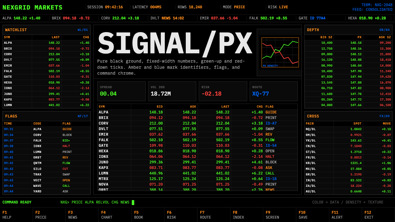 Financial Terminal MonoMaximum signal per pixel. Pure black, IBM Plex Mono, green-red ticks, amber-b…
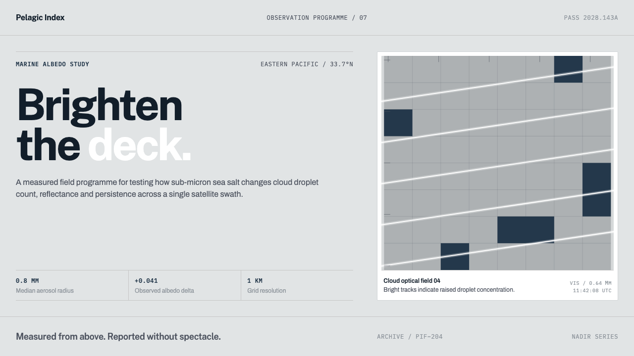 Cloud Brightening FleetBrightening becomes evidence. White ship-track lines score a cool-grey satell…
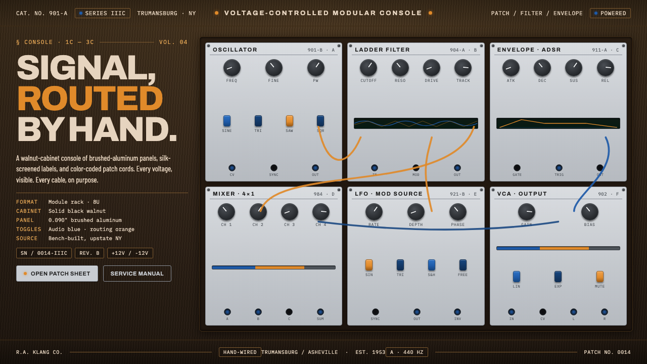 Moog Modular SynthWalnut cabinet, brushed-aluminum panels. Toggle-blue switches, orange patch c…
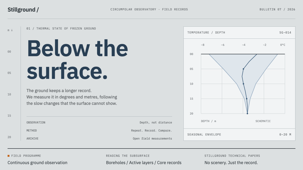 Permafrost Monitoring NetworkDepth sets the order. Overcast greys, slate profiles and hairline rules keep…
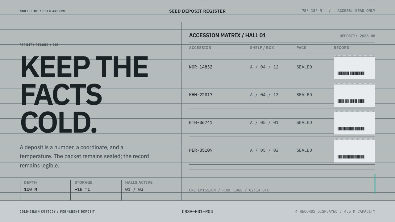 Climate Refuge Seed ArchiveFacts stay cold. Concrete-grey accession rows meet one turquoise fibre-optic…
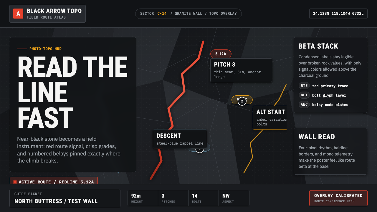 Climbing Topo GuideBeta at a glance. Red route telemetry cuts across near-black stone and conden…