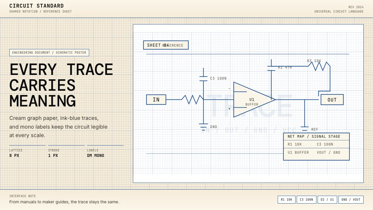
About Electrical Schematic Wiring
The electrical schematic is engineering's oldest universal visual language — a vocabulary of zigzag resistors, parallel-line capacitors, and triangle diodes standardized across IEEE, IEC, and ANSI since the 1920s. Every Heathkit manual, every NASA wiring diagram, every Arduino tutorial speaks this same graphic dialect.
This system translates that tradition into a digital design language: graph-paper cream backgrounds, ink-blue hairline connections, monospace component labels, and the austere clarity of an engineering document where every line carries meaning.
- Origin
- International (IEEE, IEC, ANSI) — originally USA + Western Europe
- Era
- 1920s standardization era; IEEE-315 1975; IEC 60617 1983; current revision 2024
- Key figures
- William Shockley · IEEE-315 Standards Committee · Heathkit manual authors · Paul Horowitz
- Movements
- 20th-century electrical engineering standardization · post-WWII consumer electronics kit culture · maker/Arduino hobbyist resurgence
Electrical Schematic Wiring design spec
Colors
Typography
The other 11 sections — buttons, cards, spacing, motion, techniques and more — open once you unlock. Download the DESIGN.md or send it to your AI in one click. Unlock once, yours forever.
Sign up nowStyles similar to Electrical Schematic Wiring
Also inspired by science & nature, with a close feel.
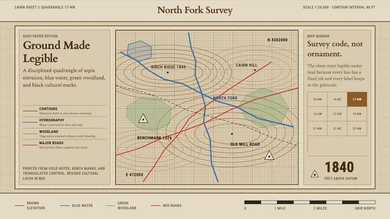 Topographic Survey MapMeasurement becomes beauty. Sepia contours and blue hydrography sit on aged map paper.
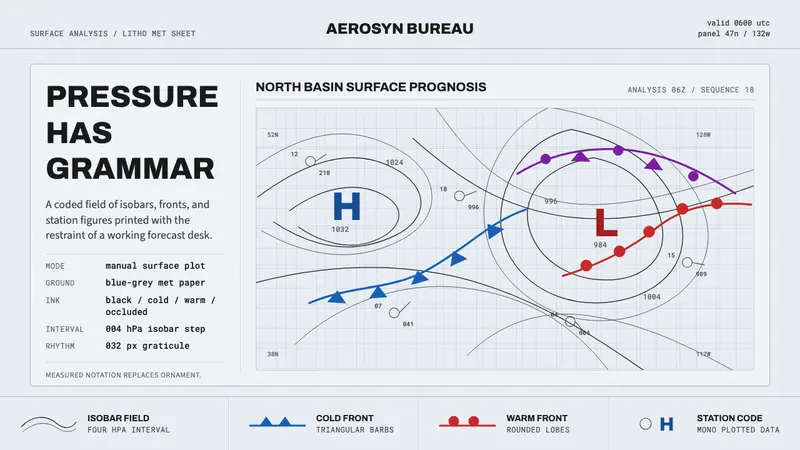 Synoptic Weather ChartPrecision reads as weather. Blue-grey graticule, thin isobars, front symbols.
 Oyster Farm (Estuary)Worked at the pace of the tide. Slate ground, brackish blue accent, grotesque sans on trestle grid.
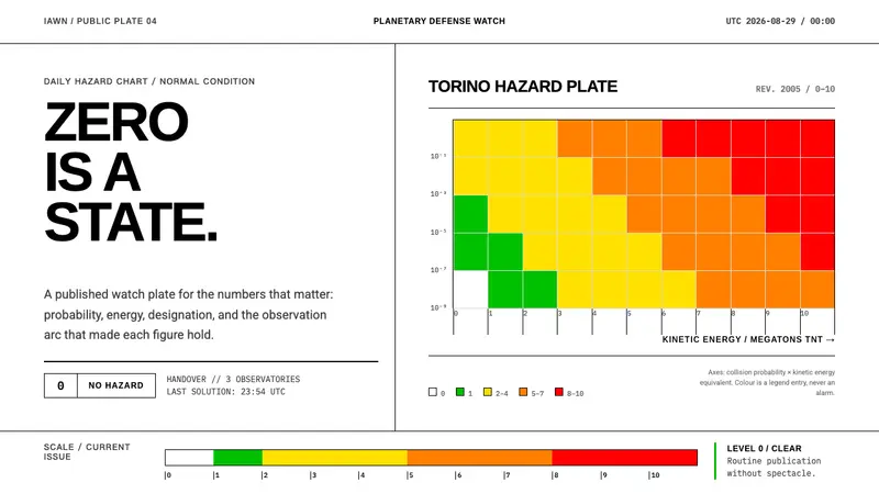 Planetary Defense WatchNothing to report is the point. Torino bands and monospace columns make risk legible.